
The following quick installation guide must be read in conjunction with the Standard Trench Box User Guide. If in doubt, contact SEL here.
Installation Sequence
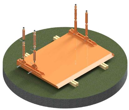

1. Lay the Trench Box panel down on a level surface on suitable timber bearers using the 4-Leg chain provided.
Connect the Spring Spindle Holders using a 40Ø Pin & R-Clip.
Connect the Adjustable spindle and appropriate extension pipes using 20Ø Pins & R-Clips.
Ensure that the lower Spindles are extended by 30-50mm more than the top Spindles.
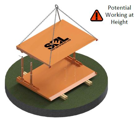

2. Lower the opposite panel onto the spindles using the 4-Leg chain.
Chain hooks to be secured to the handling points at the upper and lower ends of each side.
Secure to spindles using 20Ø Pins & R-Clips.
Do not remove slack in the chains until all the spindles are secured.
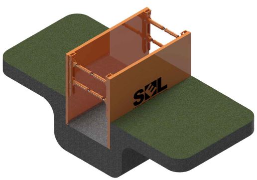

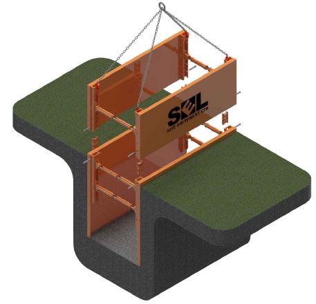
3. Lift the box into an upright position using the 4-Leg chain secured through the upper handling points.
Lower the box into a pre-excavated trench (max. 1.25m – soil stability assessed by the Contractor).
Fill and compact any gaps outside the box.
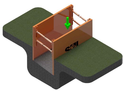

4. Excavate within the box up to 500mm deeper.
Using the excavator bucket, push the top of the panel down.
Do not batter the box or push the spindles. Note that the spindles must not exceed +/-8° rotation.
Do not enter the trench until the box is fully installed.
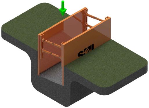

5. Repeat stage 4 on the other side of the box and alternatively Dig & Push the box to the required depth.
Smaller incremental steps are better for the shoring.

6. Where required, lower on a top box (assembled similar to stage 1) and connect using the Box Connection Unit and 40Ø Pins & Clips in each corner – see Detail A.
Continue the Dig & Push sequence as before.
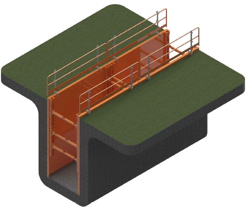

7. Install suitable edge protection and access where required. Ensure that the open end of the excavation is battered to a safe angle as determined by the Contractor or closed with suitable end closure.
Removal
The removal of the boxes should be performed sequentially. Once the permanent works are installed, the contractor should backfill inside the box in layers not exceeding 500mm.
Once the backfill is compacted to the Permanent Works design standard, the box can be lifted by a maximum of 500mm or +/-8° Spindle angle.
Continue the removal of the box sequentially in the reverse of the installation procedure until the boxes can be removed completely.
Need Help?
If you need further advice, technical or practical, we will be happy to help. Give one of our team a call today on 0117 982 8236.


