Lite Drag Box Installation Guide
The following quick installation guide must be read in conjunction with the Lite Drag Box User Guide. If in doubt, contact SEL here.
Installation Sequence
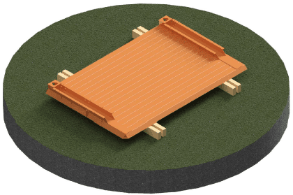
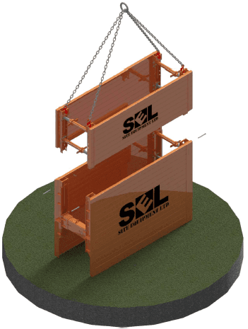
- Lay Drag Box panel down on a level surface on suitable timber bearers using the 4-Leg chain provided. Secure the lifting hooks through the handling points at the upper and lower ends of the channels.
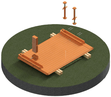
- Spin out Spindles to the required length and position into the channels alternating as shown. Secure using Pins & R-Clips as shown in .
Secure the Collar using 4no M12x40 Bolts. Insert the correct length Distance Pipe and fix using an M20x200 Bolt.
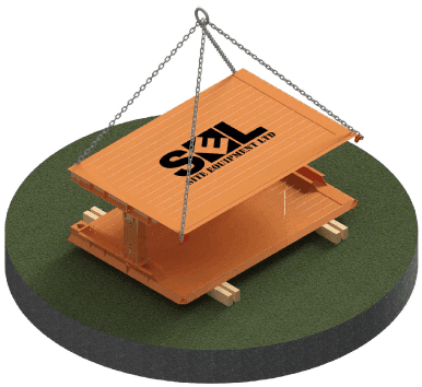
- Lower opposite panel onto spindles using the 4-Leg chain. Chain hooks to be secured to the handling points at the upper and lower ends of each channel.
Secure to spindles as Stage 2. Do not remove slack in the chains until all the spindles are secured
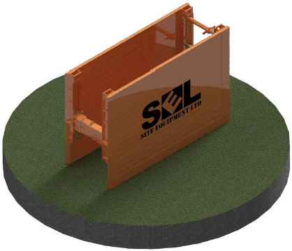
- Lift box into upright position using the 4-Leg chain secured through the upper handling points. For narrow drag boxes, it is recommended to temporarily place the box into a shallow flat bottomed trench for stability.
- Where required, lower Top Box onto Base Box (assembled similar to Stages 1-4). Secure to Base box using Pins & R-Clips as shown in .
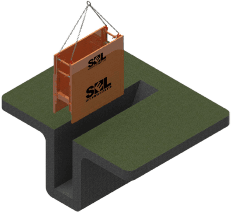
- Lift box into preformed trench excavated in . A competent person should assess the ground conditions, ensuring that the ground is temporarily stable and self supporting. A minimum 50mm upstand is recommended.
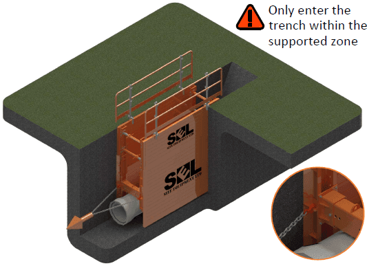
- Excavate the leading trench and drag the box using two chain legs fixed to the handling points on the cutting edge. Rather than tracking the machine, use the excavators hydraulic arm to drag the box. Once the box is in the next location, adequately backfill the previous trench ensuring a safe batter slope remains.
Removal
The removal of the boxes should be performed sequentially. Once the end of the run is reached, the contractor should backfill inside the box in layers not exceeding 500mm.
Once the backfill is compacted to the Permanent Works design standard, the box can be lifted by a maximum of 500mm. If required, use a single chain leg to pull each corner of the box slightly before attempting to lift the whole box using the 4-Leg chain.
Repeat this process until the boxes can be removed completely.
We can help with your next project.
Our team is friendly, knowledgeable and ready to consult. We offer complimentary site visits, fast delivery and competitive rates. Simply fill in the form and we'll be in touch.
You can also give us a call at any time.