
 Contact us


Slimshore Propping and Needling for Column Removal in a Hotel, Paddington, London
Location: Paddington, London
Project: Hyatt Place
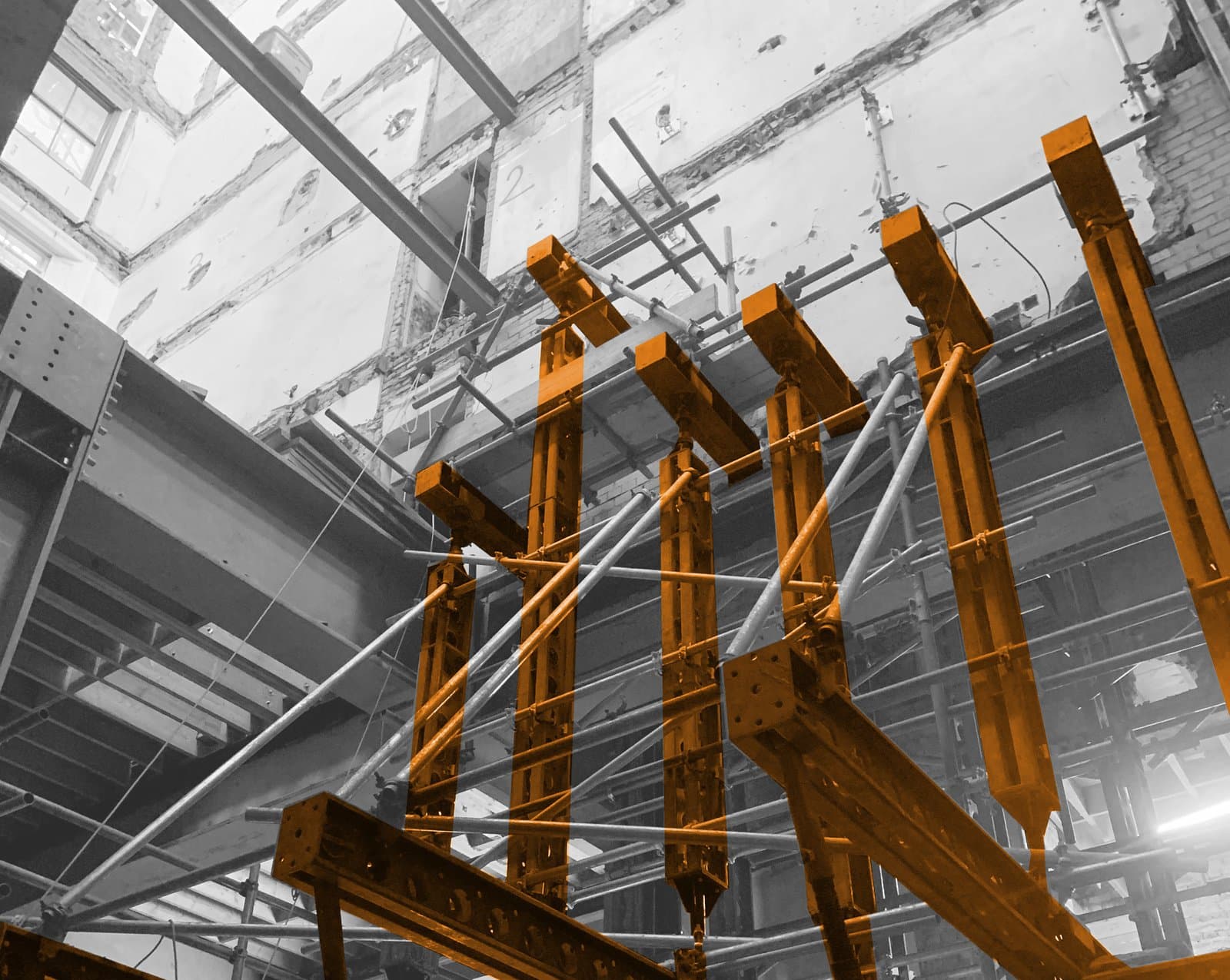
SEL provided Temporary Works Design (TWD) and supplied Slimshore propping and needling for the refurbishment of a hotel under a conservation notice in Paddington, London, where a primary ground-floor column supporting approximately 20m² across seven upper floors was permanently removed and replaced by 900mm-deep transfer steels. The needling also carried high-level lifting points, from which the new steel beams, weighing up to 2.5 tonnes, were raised into position at heights of up to 8.5m. The scheme was designed to BS 5975 with a Category 2 design check.
The hotel is subject to a conservation notice, so the existing structure of the unoccupied building had to be retained and altered rather than rebuilt behind a retained façade. To create a more open entrance foyer, the contractor relocated a lift shaft from the centre of the building to a party wall and removed a primary column at ground floor level. Each alteration needed its own structural propping or needling design. The existing timber floors were also found to need replacement once work had started.
In all, SEL supplied 43.4 tonnes of shoring and needling equipment for multi-level floor propping, dead shoring, reverse needling and further structural needling, with Slimshore plan bracing also covered in the design. At the front of the building, existing steels were used to support the needling, which avoided propping down through the basement and kept access open through the main entrance.
How Was a Ground-Floor Column Supporting Seven Floors Removed Using Slimshore Needling?
The column stood in the foyer behind the main entrance and supported approximately 20m² on each of the seven floors above. Its load had to be transferred into temporary works before it could be removed and replaced by 900mm-deep transfer steels within a floor-to-floor height of 3.54m.
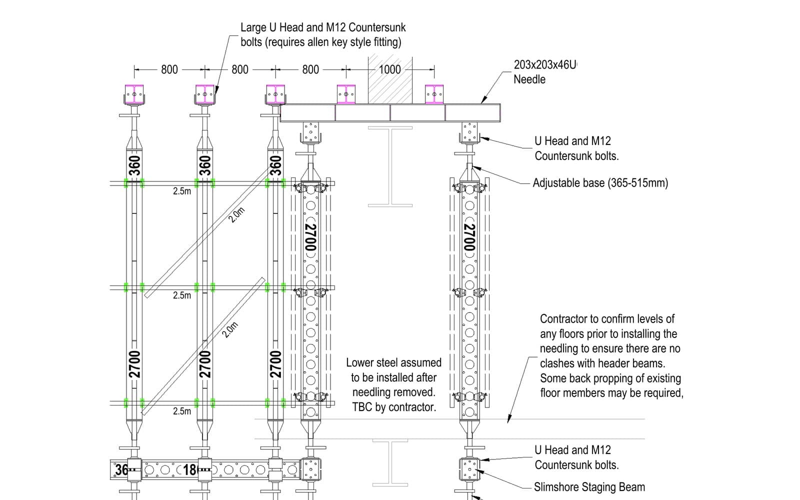
SEL designed two-tier Slimshore needling along the line of the column. The 203 UC needle beams were carried on Slimshore soldiers from a staging beam, and the lower soldiers were founded partly on the new permanent pad foundation. Raking Slimshore soldiers and push-pull props provided lateral restraint. The design allowed a UDL of 260kN/m and a maximum needle point load of 195kN. The maximum prop load was 98kN and the predicted vertical displacement 5.9mm. The needling was installed in phases as the permanent works progressed.
How Did the Needling Provide Lifting Points for 2.5-Tonne Steel Beams?
The contractor asked for the temporary propping and needling to incorporate higher-level lifting points, so that the new steel beams could be raised into position from the temporary works. In the column-removal arrangement, two needles were set above the main needle level to act as lifting points. Propping heights reached up to 8.5m from the basement floor to the lifting points, and the heaviest beams lifted weighed 2.5 tonnes.
Why We Used Existing Steels to Support Needling at the Front of the Building
At the front of the building, two existing steels ran either side of the position of a new steel beam. Both stayed in place while the new beam was installed and were removed afterwards. SEL designed the needling to stand on their top flanges instead of propping down through the basement. Eight 203 UC needles were installed at centres of no more than 750mm, and the two end needles were designed to share an additional 25kN for lifting the 2.5-tonne beam.
Using the existing steels simplified the needling in this area. It also kept the front of the building clear of props, whereas a full propping arrangement down to the basement would have restricted access through the building for the rest of the works.
How Was Multi-Level Propping Designed to Remove a Wall Supporting Four Floors?
Beside one of the staircases, floor joists at four levels were built into a wall that had to be demolished and rebuilt. The affected length was approximately 5.3m. Access was restricted to around 1m of working space on the boundary side, and the staircase limited prop positions on the other.
SEL's propping design used 40 adjustable props and 64 H20 beams to pick up the floors independently on both sides of the wall through all four levels. The floor load was therefore carried by the temporary propping before demolition began. The design allowed 2.5kN/m² at each floor. Because each prop line also carried the floors above it, the design line load increased from 6.5kN/m at third floor to 26kN/m at ground floor.
Where Were Dead Shoring and Reverse Needling Used in the Hotel?
A Slimshore dead shore of four soldier props carried an unfactored load of 170kN from an existing beam near the new lift shaft position. On one two-storey wall line, the needling relied on an existing steel for lateral stability, and secondary propping supported a vaulted ceiling below. Another needling arrangement stood on sacrificial foundations, taken deep enough not to be undermined by the excavation for a new pad foundation beside them. A 4m opening at the rear of the building was needled with 152x152 UC needle beams. Where reverse needling was used, the props were founded on lower needles through the wall below, so the wall beneath carried the temporary load.
How Does Slimshore Plan Bracing Maintain Lateral Stability During Floor Replacement?
Removing large areas of timber floor at once would take away the restraint the floors give to the walls. SEL designed a Slimshore plan brace so that larger areas of flooring could be replaced at a time while the lateral stability of the building was maintained. Slimshore soldiers act as walers along the walls, tied through the masonry and braced diagonally across the floor plate with push-pull props, restraining the party wall around the new lift shaft position.
Design Criteria for the Slimshore Propping and Needling
| Design criterion | Project requirement |
|---|---|
| Column removal needling UDL | 260kN/m |
| Maximum needle point load | 195kN |
| Maximum prop load | 98kN |
| Dead shore beam load (unfactored) | 170kN |
| Reverse needling UDL | 130kN/m |
| Multi-level floor loading | 2.5kN/m² per level |
| Maximum steel lift weight | 2.5 tonnes |
| Maximum height to lifting points | 8.5m |
| Design standard | BS 5975 |
| Design check category | Category 2 |
The Result:
The Slimshore needling carried the load from seven upper floors while the ground-floor column was removed and the 900mm-deep transfer steels were installed. The steel beams, weighing up to 2.5 tonnes, were lifted into position from lifting points built into the temporary works at heights of up to 8.5m. Supporting the needling on existing steels at the front of the building kept access open through the main entrance. Multi-level propping allowed a wall supporting four floors to be demolished and rebuilt with restricted access. Dead shoring and reverse needling supported the lift shaft relocation and the timber floor replacement within the retained structure.
Services and Equipment Provided
- Temporary Works Design (TWD) to BS 5975, Category 2 check
- Propping and needling design
- SEL Slimshore soldiers, staging beams and header beams
- 203x203 and 152x152 UC needle beams
- Slimshore plan bracing
- Push-pull and raking props
- Adjustable props and H20 timber beams
- Project-specific engineering support
Other Applications for Slimshore Propping and Needling
- Forming large structural openings in existing buildings
- Removal of loadbearing walls and columns
- Supporting structures during permanent steel installation
- Beam and column replacement
- Basement construction and underpinning
- Phased demolition and refurbishment
- Façade and retained-wall support
- Temporary support around stair and lift openings
- Transferring loads where conventional prop positions are unavailable
Need Propping and Needling for Column Removal or a Structural Alteration?
The Slimshore propping and needling for this project was supplied from SEL's London depot. SEL's in-house engineers provide Temporary Works Design and engineering support for column removal, structural alterations, refurbishment and the formation of openings in existing buildings, whether SEL is supplying a full design and supply package or equipment only. Contact the London depot or your nearest SEL depot to discuss your project or arrange a no-obligation site visit.
Gallery

We can help with your next project.
Our team is friendly, knowledgeable and ready to consult. We offer no-obligation site visits, fast delivery and competitive rates. Simply fill in the form and we'll be in touch.
You can also give us a call at any time.