
 Contact us


High-Capacity Slimshore Propping for Basement Structural Alterations, Norwich
Location: Norwich
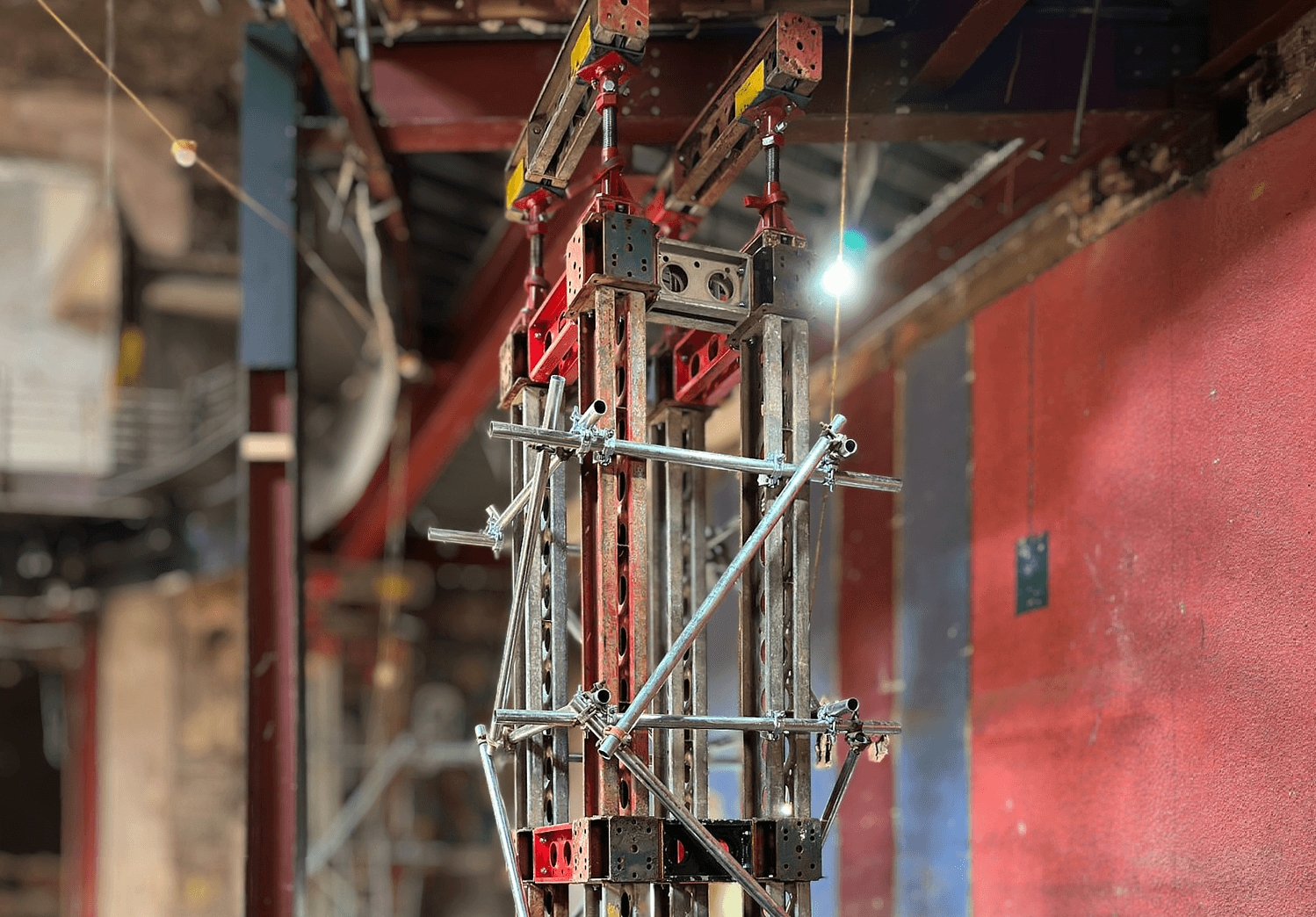
SEL designed and supplied 10 high-capacity Slimshore propping towers to support retained slabs and beams during major structural alterations in the basement of an existing building in Norwich. The most heavily loaded tower was designed for a maximum vertical unfactored load of 160kN. Limited plant access to the basement restricted individual components to 40kg, so the towers were assembled largely by hand from lightweight modular Slimshore sections. The propping allowed masonry walls and reinforced concrete slab sections to be removed and a new lift shaft installed while the retained structure remained supported.
The works involved extensive alterations to the existing structure, including the installation of a new lift shaft, the removal of masonry walls and the removal of sections of reinforced concrete slab. As these elements were taken out, parts of the retained structure could no longer rely on their original load paths, so slabs and beams needed temporary support until new permanent steelwork and associated structural elements had been installed and were capable of carrying the loads independently.
SEL provided the Slimshore propping design, Temporary Works Design calculations to BS 5975, Category 2 design checking, Slimshore equipment hire and detailed assembly drawings.
The Challenge: High Loads and Limited Mechanical Handling in a Basement
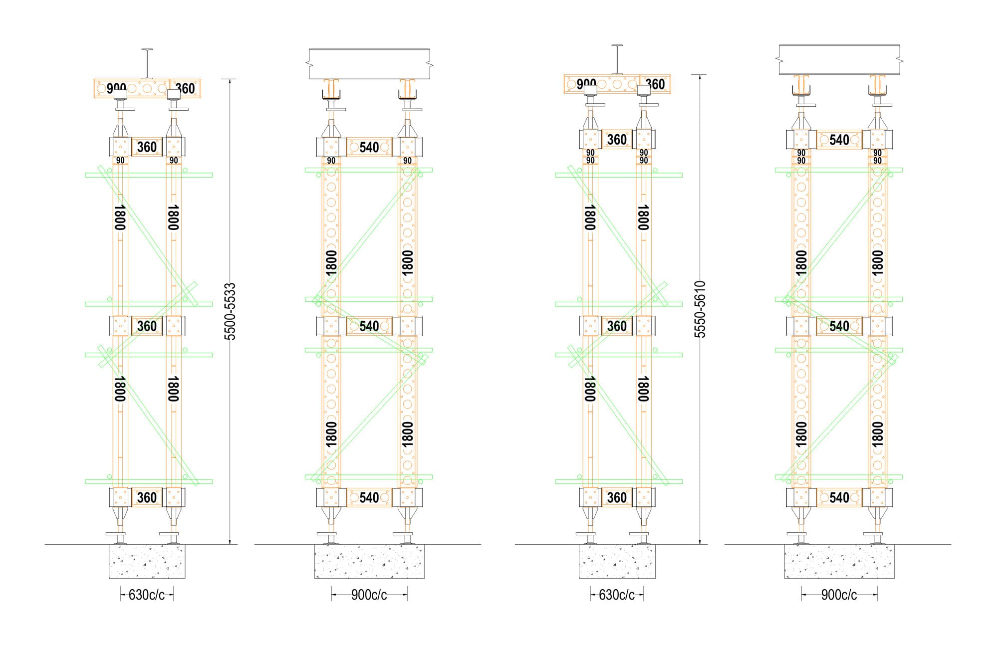
The project team identified 10 separate areas requiring temporary support, each using a similar four-legged Slimshore tower arrangement. The towers were between 5.5m and 5.8m high and were all substantially loaded, with the most heavily loaded location designed for a maximum vertical unfactored load of 160kN (approximately 16 tonnes).
The towers were located below ground in the basement of the existing building, where the contractor could make only limited use of plant and mechanical handling. Individual components were therefore restricted to a strict 40kg manual-handling limit, and the temporary works had to provide substantial support from modular elements light enough to be carried into the basement and assembled largely by hand.
Slimshore Propping Design Criteria
| Design criterion | Project requirement |
|---|---|
| Location | Basement of existing building |
| Tower height | 5.5–5.8m |
| Maximum vertical unfactored load | 160kN (approximately 16 tonnes) |
| Tower arrangement | Four-legged Slimshore tower |
| Tower footprint | 630mm × 900mm centres |
| Six-way connector levels | 3 per tower |
| Maximum individual component weight | 40kg |
| Maximum soldier section used | 1.8m / 38.8kg |
| Calculated maximum elastic shortening/deflection | 2mm |
| Foundations | Prepared concrete bases |
| Temporary Works Design standard | BS 5975 |
| Design check | Category 2 |
The combination of substantial support loads, tower heights of more than 5.5m and the strict manual-handling restriction meant that equipment selection and buildability were central to the Temporary Works Design.
Why We Limited Slimshore Soldier Sections to 1.8m
The 40kg component-weight restriction imposed by the basement access conditions directly influenced the Slimshore configuration. A 1.8m Slimshore soldier weighs 38.8kg, placing it just inside the project limit, while the next standard lengths — 2.7m at 55.4kg and 3.6m at 72.2kg — exceeded the permitted manual-handling weight.
The towers therefore had to be built up from 1.8m soldier sections rather than using longer members that would have required greater mechanical assistance, with the sections connected end to end using bolted joints. Slimshore was particularly well suited to this requirement because its modular construction allowed high-capacity towers more than 5.5m high to be assembled from relatively lightweight individual components.
The compact 630mm × 900mm tower footprint also helped keep the arrangement practical within the existing structure, while heavy-duty jacks allowed the completed towers to be adjusted accurately once assembled.
How the Slimshore Towers Were Configured and the Loads Transferred
Each support location used a similar four-legged Slimshore tower formed from soldier sections, six-way connectors and horizontal spacer soldiers. Three levels of six-way connectors and horizontal members tied each tower together, while heavy-duty base jacks provided adjustment at both the top and bottom.
The lower jacks were founded onto prepared concrete bases, with the towers fixed down to maintain stability throughout the temporary condition. Secondary scaffold tube and fittings were also incorporated as part of the overall stability arrangement.
At the head of each tower, the upper jacks supported Slimshore header beams seated in U-heads, which picked up the retained slabs and beams above. The loads were then transferred through the four-legged towers and soldier sections into the prepared concrete bases, providing a direct temporary load path while demolition and permanent works progressed.
No preloading or jacking of the Slimshore system was required before demolition began.
Installation and Striking Sequence
The works began with the casting of prepared concrete bases at each tower location, after which the Slimshore towers were assembled in situ in accordance with SEL’s temporary works drawings. Adjustable push-pull props were used during erection to support and align the soldier sections while each tower was being built.
Once the propping was complete and capable of carrying the identified loads, the contractor proceeded with the removal of masonry walls and sections of reinforced concrete slab. The Slimshore remained in place throughout the structural alteration works until the new permanent steelwork and associated structural elements had been installed and were capable of supporting the retained structure independently, after which the towers were dismantled in the reverse sequence to their installation.
Temporary Works Design to BS 5975
SEL provided the engineering design for the propping scheme as well as the Slimshore equipment. Detailed drawings gave the contractor clear assembly information and identified the significant issues that needed to be considered throughout the life of the temporary works, while hazards and residual risks were also set out so they could be incorporated into the contractor’s own planning and risk assessments.
Temporary works calculations confirmed that the proposed towers had sufficient capacity for the specified loads and that movement remained within acceptable limits, with a calculated maximum elastic shortening/deflection of 2mm. The design was undertaken in accordance with BS 5975 and subjected to a Category 2 design check.
No changes to the propping arrangement were required once the existing structure was exposed.
The Result: Temporary Support Across Ten Structural Alteration Zones
The completed scheme provided temporary support at all 10 locations while extensive structural alterations were carried out in the basement of the existing building. Using similar four-legged Slimshore arrangements throughout gave the contractor a consistent solution across the project while still allowing the individual towers to accommodate the differing structural loads at each position.
With tower heights of 5.5–5.8m, a maximum vertical unfactored load of 160kN, a compact 630mm × 900mm footprint and a strict 40kg component-weight limit, the scheme allowed the structural alteration works, including the new lift shaft installation and removal of masonry and reinforced concrete elements, to proceed while the retained structure remained supported.
Services and Equipment Provided
- Temporary Works Design and calculations
- Slimshore propping design
- BS 5975 Category 2 design check
- SEL Slimshore soldier members
- Slimshore header beams
- Six-way connectors
- Heavy-duty base jacks & U-heads
- Bolted soldier connections
- Scaffold tube and fittings
- Adjustable push-pull props
- Detailed assembly drawings & risk data
Other Applications for Slimshore Soldiers
Slimshore soldiers and the propping and needling approach more generally can also be used for:
- supporting retained slabs and beams during structural alterations
- temporary support during permanent steel installation
- removal or replacement of loadbearing walls
- beam and column replacement
- lift and stair-core formation in existing buildings
- propping and needling for large structural openings
- façade retention and support to retained elevations
- phased demolition and major refurbishment
- basement construction and underpinning
- high-capacity propping where access or manual-handling restrictions limit the use of plant
Need Slimshore Propping for Structural Alterations?
SEL supplies Slimshore propping systems for hire, supported by in-house temporary works engineering for refurbishment, demolition, structural alterations and temporary support to retained structures.
Our engineers can develop project-specific propping arrangements where factors such as high loads, restricted access, limited mechanical handling or complex construction sequencing make a standard support arrangement impractical.
Contact your nearest SEL depot to discuss your project or arrange a no-obligation site visit.
Gallery

We can help with your next project.
Our team is friendly, knowledgeable and ready to consult. We offer no-obligation site visits, fast delivery and competitive rates. Simply fill in the form and we'll be in touch.
You can also give us a call at any time.