
 Contact us


Dokaflex 124 Soffit Support System Installation Guide
How to erect and strike the Dokaflex 124 Soffit Support System, the hand-set timber-beam falsework we hire for concrete slabs and soffits.
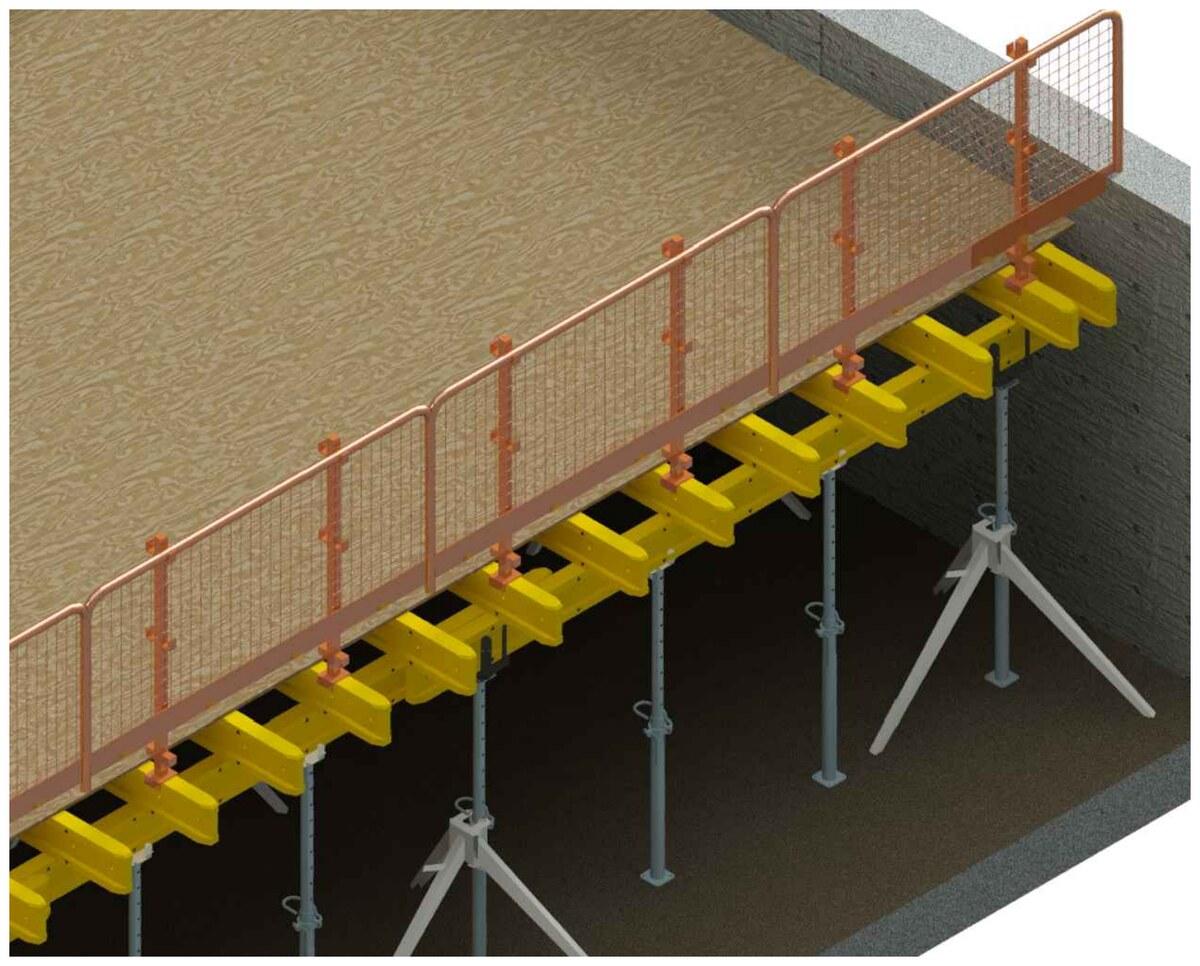
You start from a corner, erecting Eurex 30 Props with Tripods and Lowering Heads on a grid, then add the H20 Primary beams, intermediate props, H20 Secondary beams and a plywood deck. The layout table below gives prop and beam spacings for slabs up to 0.50m thick. To strike the system, you work from below the deck on a suitable moveable scaffolding tower, remove the intermediate props and then hit the Lowering Heads with a hammer, which drops the entire deck. This guide also covers lateral restraint, drop beams and slab edges.
If you'd like a printable copy, download the Dokaflex User Guide (PDF). For full specifications, see the Dokaflex 124 Soffit Support System product page.
Dokaflex Component Weights
| Item | Weight |
|---|---|
| Eurex 30 Prop (2.50m) | 14.8kg |
| Eurex 30 Prop (3.0m) | 16.7kg |
| Eurex 30 Prop (3.5m) | 20.5kg |
| 1.80m H20 Beam | 9.5kg |
| 2.65m H20 Beam | 14.1kg |
| 2.90m H20 Beam | 15.4kg |
| 3.30m H20 Beam | 17.5kg |
| 3.90m H20 Beam | 20.7kg |
| 5.90m H20 Beam | 31.3kg |
| Tripod | 15.6kg |
| Lowering Head | 6.1kg |
| Supporting Head | 0.77kg |
Recommended System Layouts
| Slab Thickness | Up to 0.30m | 0.35m | 0.40m | 0.45m | 0.50m |
|---|---|---|---|---|---|
| Applied Load | 9.66kN/m² | 11.22kN/m² | 12.78kN/m² | 14.34kN/m² | 15.9kN/m² |
| Secondary Beam Spacing | 0.50m | 0.45m | 0.40m | 0.40m | 0.40m |
| Primary Beam Spacing | 2.00m | 2.00m | 2.00m | 1.75m | 1.50m |
| Prop Spacing | 1.00m | 1.00m | 0.75m | 0.75m | 0.75m |
For slab thicknesses greater than 0.50m, please contact SEL for advice.
Installation Sequence
1. Erect the props
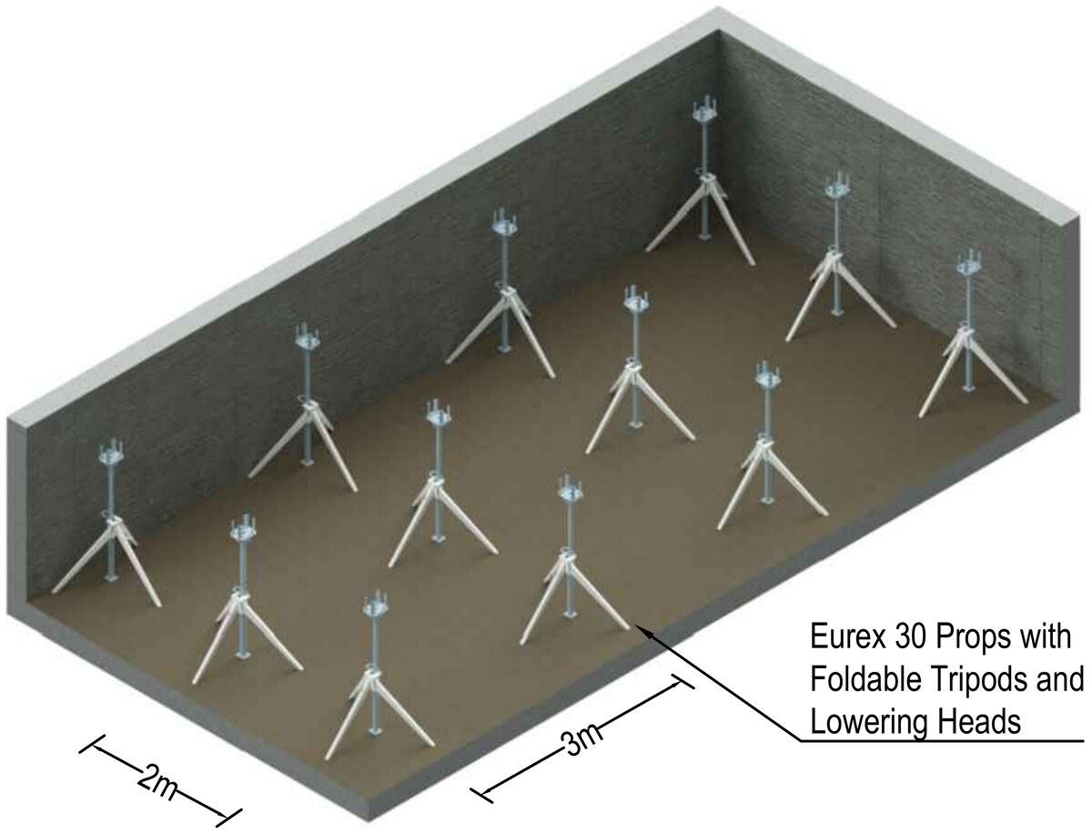
Starting from a corner, erect Eurex 30 Props with Tripod support on a grid of 2m by 3m (for slabs up to 300mm thick; for thicker slabs see 'Recommended System Layouts' table for closer prop spacings).
Equip each Eurex 30 Prop with a Lowering Head in the open (taller) position.
Set prop height (inc. head) to be 418mm less than the soffit height. Adjust for the plywood deck thickness (18mm assumed).
Edge props to be max. 500mm from the surrounding walls.
2. Install the primary beams
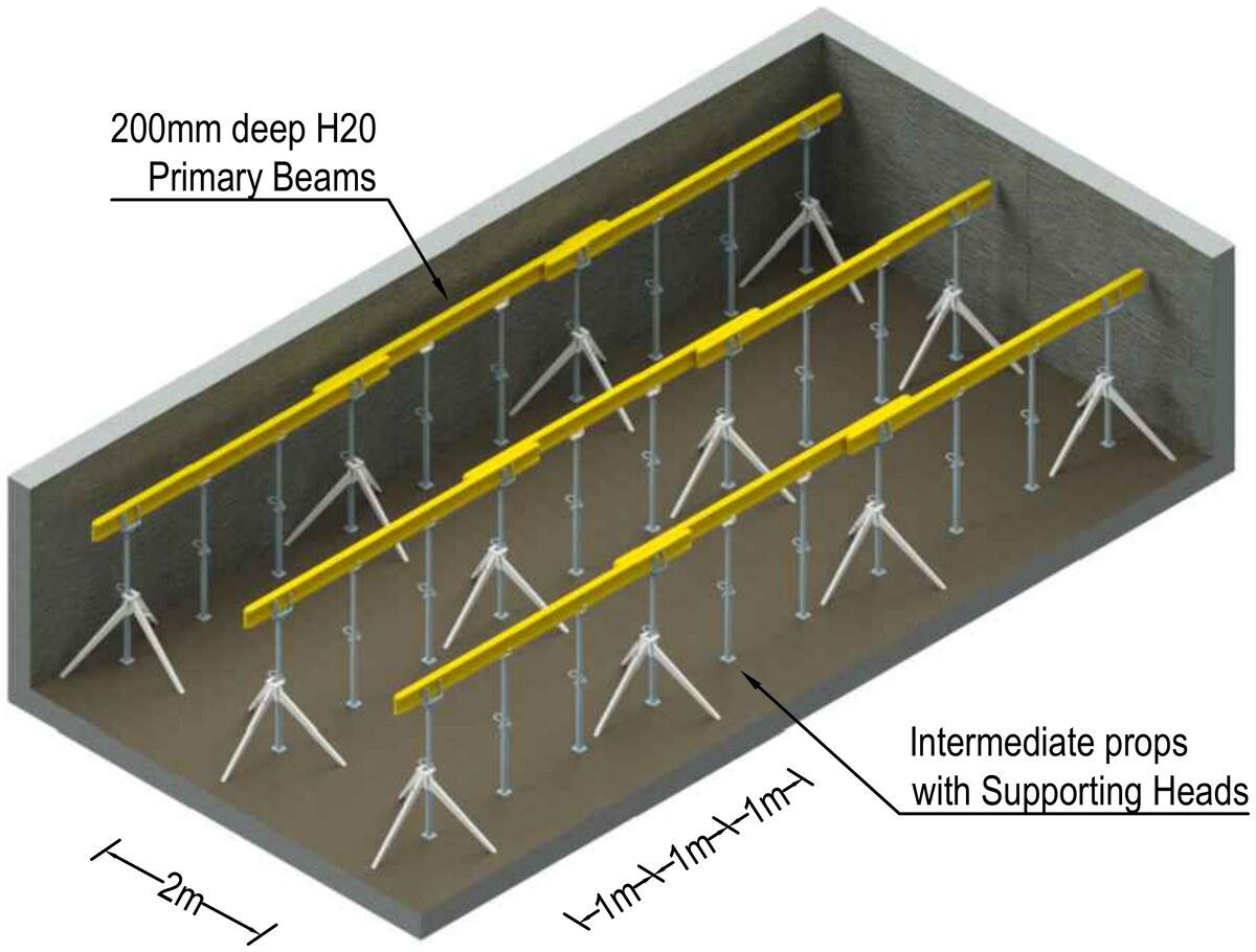
Install the 3.9m Primary H20 timber beams between Lowering Heads, leaving an equal overhang on each end of the beams.
Erect the intermediate supporting props at 1m centres and equip with Supporting Heads.
3. Install the secondary beams
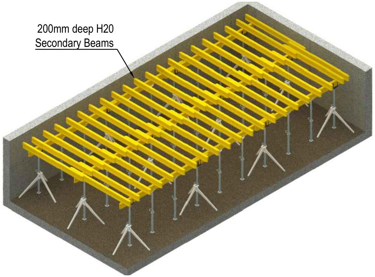
Install the 2.65m H20 Secondary beams at 0.5m (one mark) centres (see adjacent table for closer secondary spacings for slabs over 300mm thick).
Install H20 Securing Clips at the intersection of every Secondary and Primary beam above the prop locations.
At column locations, place H20 Secondary beams either side of the column and install additional supporting timber where the gap exceeds 0.50m. Secure the plywood deck around the column with additional timber where required.
4. Install the deck and edge protection
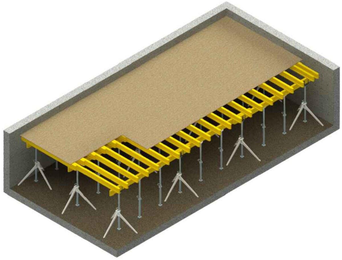
Install suitable decking plywood (not supplied by SEL).
Suitable edge protection must be installed on all sides of the deck where required. Site Equipment's Edge Safe barrier system can be installed on both Primary and Secondary beams with accompanying barriers.
Lateral Restraint
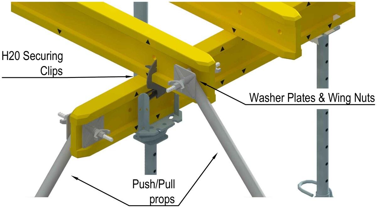
The Dokaflex system is designed as a 'Top Restrained System'. The primary method of providing lateral restraint is to install the decking tight against completely surrounding walls and internal columns.
Where this is not possible, Push/Pull props can be secured to the Primary and/or Secondary H20 beams using tie bar, washer plates and wing nuts.
Striking the System
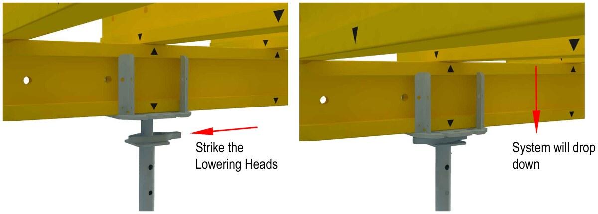
The entire system should be removed from below the deck, utilising a suitable moveable scaffolding tower.
- Remove all intermediate props (with Supporting Heads) and H20 Securing Clips.
- Lower the Dokaflex deck by striking the Lowering Heads with a hammer. The entire deck will drop down.
- Turn the Secondary beams onto their sides and remove. Leave all Secondary beams below plywood deck joints in place.
- Remove plywood deck panels.
- Remove remaining Secondary beams and all Primary beams.
- Remove all Foldable Tripods and remaining props (with Lowering Heads).
NB: Stipulated striking times must be managed by the Contractor.
Drop Beams & Slab Edges
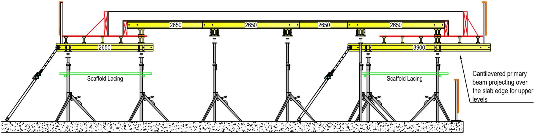
Drop beams can be accommodated using the Dokaflex system by incorporating a lower deck upon which the main slab deck can sit.
Working room can be allowed to the side of the slab allowing for the drop beam formwork to be installed. Lateral restraint in both directions must be provided.
For the upper levels, the slab edge 'Table' must utilise a longer cantilevered Primary beam which is tied down to the main floor slab using Push/Pull props to ensure stability.
Depending on the geometry and overhang required, the Primary beams may need to be twinned to ensure adequate strength.