
 Contact us


Waler Frame Excavation Support for the Old Market District Heating Network, Bristol
Location: Old Market, Bristol
Project time: 2019–2020
SEL supplied the trench support for around 1,000 metres of the Old Market district heating network in Bristol. Our engineers produced the temporary works design (TWD) for 140m of trenches, beside a historic stone harbour wall and scaffolding. At Castle Park, we used standard trench sheets and 4m hydraulic aluminium waler frames, with thickened blinding replacing the lower frame for pipe laying. On Marshall Street, pre-driven KD6 trench sheets and paired 2m waler frames on the lower level carried a massive 82 kN/m² scaffold surcharge.
District Heating Main Installation in Bristol's Old Market
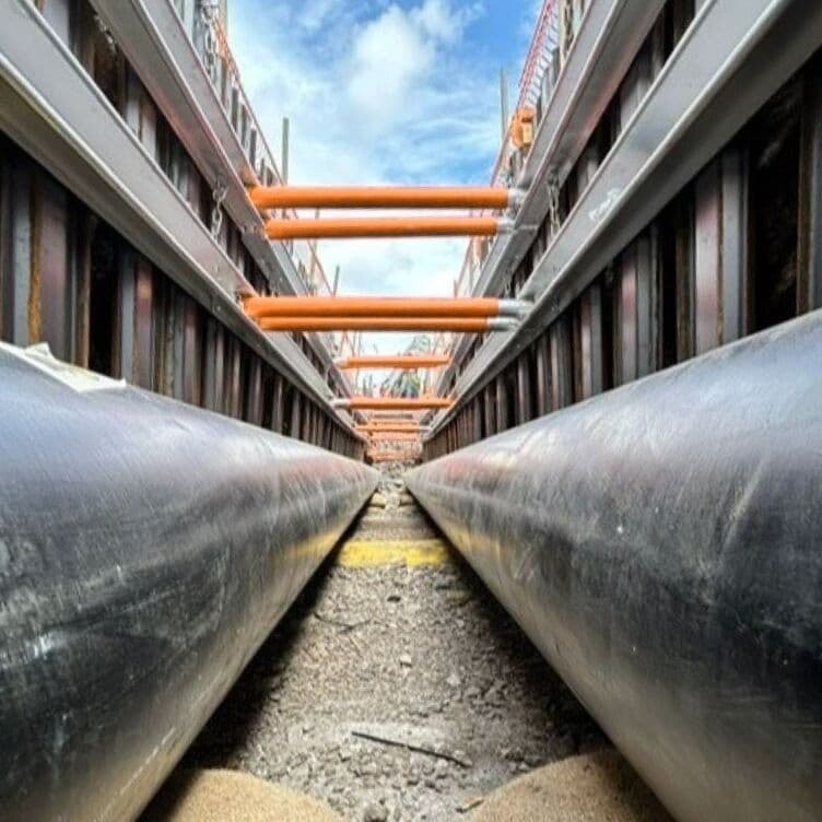
The Old Market district heating network is a buried heat network of approximately 1,000 linear metres serving the Old Market East and West areas of Bristol, including Castle Park. Twin 450mm flow and return pipes were laid side by side in a shared trench, with branch connections serving new developments and extending to two temporary energy centres. The pipes were laid and welded inside the open excavation, so the trench support had to protect the pipe-laying gangs from collapse along the full length of each run.
Most of the pipe trenches on the scheme used a standard trench shoring arrangement. SEL supplied the trench sheets and waler frames for the scheme, along with engineered excavation support designs for the sections where an adjacent structure or surcharge took the requirement beyond that standard arrangement.
The Challenge: Trench Support Beside a Stone Harbour Wall and a Scaffold Surcharge
At Castle Park, the 40m trench ran parallel to an old stone harbour wall approximately 3.5m from the excavation, with formation close to the level of the top of the wall. Little was known of the wall's construction beyond its stone masonry. The ground was tarmac over clay-bound compact made ground of stone, gravel and brick, in an area bombed during the Second World War, and no groundwater was expected. The pipes had to be laid beneath the frames, so the trench needed clear space below the upper frame at formation.
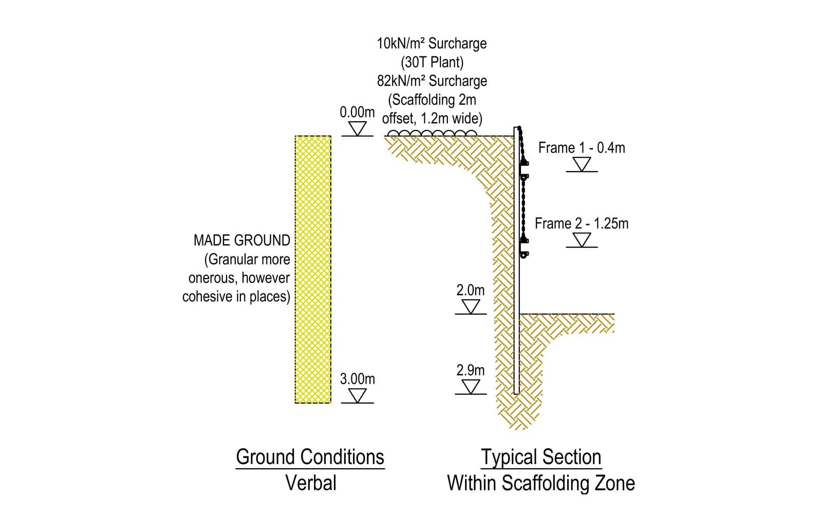
On Marshall Street, 20m of a 100m trench ran alongside a building under multi-storey scaffolding. For design purposes, the scaffold load was treated as a 1.2m-wide strip surcharge of 82 kN/m² at 2m from the trench edge. This significantly exceeded the general 10 kN/m² allowed for construction activities throughout the rest of the project. The ground there was made ground, granular in most places and cohesive in others. The trench was already open and needed to be backfilled so the road could be crossed, which meant the excavation support design had to use equipment available for immediate delivery.
On both sections, the 4m bay length suited the pipe lengths, and other waler frame lengths could obstruct pipe installation.
| Design criterion | Project requirement |
|---|---|
| Trench length | 40m (Castle Park), 100m (Marshall Street) |
| Trench width | 2.0m (Castle Park), 1.8m (Marshall Street) |
| Formation depth | 1.8m (Castle Park), 2.0m (Marshall Street) |
| Sheet toe depth | 2.1m (Castle Park); 2.9m beside scaffold, 2.4m elsewhere (Marshall Street) |
| Distance to stone harbour wall | Approximately 3.5m (Castle Park) |
| Ground conditions | Clay-bound compact made ground of stone, gravel and brick (Castle Park); made ground, granular, cohesive in places (Marshall Street) |
| Groundwater | None expected |
| Plant surcharge | 10 kN/m² (plant up to 30 tonnes) |
| Scaffold surcharge | 82 kN/m², 1.2m wide, 2m offset (Marshall Street) |
| Frame levels | 0.5m and 1.2m (Castle Park); 0.4m and 1.25m (Marshall Street) |
| Maximum frame load | 11.5 kN/m (Castle Park); 23.3 kN/m upper, 37.6 kN/m lower (Marshall Street) |
| SWL, 4.0m aluminium waler frame | 30.5 kN/m |
| SWL, 2.5m aluminium waler frame | 48 kN/m |
| Maximum sheet bending moment | 3.2 kNm (Castle Park); 11.4 kNm (Marshall Street) |
| Sheet bending moment capacity | 8.5 kNm standard trench sheet; 43.5 kNm KD6 trench sheet |
| Design check category | Category 2 |
Why Standard Trench Sheets and 4m Waler Frames Were Used Beside the Harbour Wall
The excavation at Castle Park ran approximately 3.5m from the stone harbour wall, and the design assessed whether the wall would add load to the trench support. The wall lay beyond a 45° line projected up from formation level, outside the zone of ground that bears on the excavation, so no additional load from the wall was applied to the trench sheets or frames.
With only the 10 kN/m² plant surcharge acting, the maximum frame load was 11.5 kN/m against the 30.5 kN/m safe working load of a 4m aluminium waler frame. The maximum sheet bending moment was 3.2 kNm against the 8.5 kNm capacity of a standard trench sheet. Standard trench sheets of 2.5m minimum length, toed to 2.1m, and two levels of 4m hydraulic waler frames at 1,640mm strut centres therefore provided the excavation support beside the wall. The 4m bay length matched the pipe lengths, as on the rest of the scheme.
Why Thickened Blinding Replaced the Lower Waler Frame at Castle Park
The lower frame at 1.2m sat within the space needed to lower and lay the 450mm pipes. Once the trench reached its 1.8m formation, a thickened blinding was cast across the base of the trench, capable of resisting a 10 kN/m line load from the trench sheets. The blinding then acted as the lower support to the sheets, so the lower hydraulic waler frame could be removed. The pipes were laid beneath the upper frame at 0.5m, and the trench was backfilled to the underside of that frame before it was struck.
Why We Used 2m Waler Frames on the Lower Level Beside the Marshall Street Scaffold
The scaffold surcharge raised the lower frame load to 37.6 kN/m, beyond the 30.5 kN/m safe working load of a 4.0m aluminium waler frame. The upper frame load of 23.3 kN/m remained within the capacity of the 4m frame.
SEL's engineers kept 4m hydraulic waler frames on the upper level and placed two 2.0m aluminium waler frames side by side on the lower level within each 4m bay, at 1,280mm strut centres. A shorter waler spans a shorter distance between hydraulic struts and so carries a higher load per metre. The arrangement increased the capacity of the lower frame level without changing the 4m bay length the pipe-laying gangs relied on. The design also allowed for 2.5m bays using 2.5m waler frames on both levels, which have a safe working load of 48 kN/m, so the configuration could follow the stock available at the time.
KD6 Trench Sheets for Excavation Support Under a Scaffold Surcharge
Within the 20m beside the Marshall Street scaffolding, 3.0m KD6 trench sheets were pre-driven to 2.9m, giving 0.9m of embedment below the 2.0m formation. The maximum sheet bending moment under the 82 kN/m² scaffold surcharge was 11.4 kNm, against a KD6 trench sheet capacity of 43.5 kNm.
Away from the scaffolding, only the 10 kN/m² plant surcharge applied, so standard trench sheets pre-driven to 2.4m were sufficient for the remaining 80m. Both frame levels used aluminium waler frames up to 4.0m long, and SEL supplied a mix of frame lengths from stock while keeping to the bay lengths the pipe gangs preferred.
Slit Trench Installation, Load Transfer and Striking
At Castle Park, the trench was first slit to 1.8m and the trench sheets installed, then backfilled with arisings. The trench was excavated to 0.7m and the upper hydraulic waler frame installed at 0.5m. At 1.2m, the sheets were pushed to their 2.1m toe, and the excavation continued to 1.4m for the lower frame at 1.2m. The trench was then taken to its 1.8m formation and the thickened blinding cast before the lower frame was removed.
On Marshall Street, all trench sheets were pre-driven before excavation began. The trench was excavated to 0.6m and the upper frame installed at 0.4m, then excavated to 1.45m for the lower frame at 1.25m, and finally taken to the 2.0m formation.
On both sections, the trench sheets span vertically between the frame levels and the embedded toe, and the hydraulic struts carry earth pressure and surcharge across the trench between opposing walers. Restraint chains secured each frame to the sheets. Striking reversed the installation sequence. The trench was backfilled to the underside of each waler frame before that frame was released and lifted out, and the trench sheets were then extracted. Both temporary works designs were independently checked to Category 2 under BS 5975.
The Result: 140m of District Heating Trench Completed Beside a Harbour Wall and Live Scaffolding
The 40m Castle Park trench beside the stone harbour wall and the full 100m on Marshall Street were completed, including the 20m section 2m from the multi-storey scaffolding. The twin 450mm flow and return pipes were laid and welded inside the shored trench, which was backfilled as the waler frames and trench sheets were struck. The 4m bay length was kept on both sections, so the pipe-laying gangs worked to the same bay arrangement throughout.
Services and Equipment Provided
- Temporary works design (TWD) for trench support beside a stone harbour wall and under scaffold surcharge, Category 2 checked
- KD6 trench sheets, 3.0m
- Standard trench sheets
- 4.0m, 2.5m and 2.0m hydraulic aluminium waler frames
- Restraint chains
- Installation kit and lifting chains
- Trench sheet extractor
Other Applications for Trench Sheets and Hydraulic Waler Frames
- Water and sewer main installation
- Gas and district heating pipelines
- Cable and duct trenches for power and telecoms
- Drainage runs and manhole installation
- Excavations beside retaining walls, quay walls and historic structures
- Excavations beside buildings, scaffolding and highway loads
- Road crossings and excavation under traffic management
- Chamber and pit excavation
- Foundation and ground beam excavation
- Utility diversions on development sites
Trench Support Design and Supply from SEL
The trench sheets and waler frames for this project were supplied from SEL's Bristol depot, which covers South West England. SEL supplies temporary works design and engineering support for excavation support and trench shoring, including excavations beside existing structures and where surcharge from scaffolding, buildings or plant takes the requirement beyond a standard arrangement. Contact the Bristol depot or your nearest SEL depot to discuss your trench support requirements or arrange a no-obligation site visit.
Gallery

We can help with your next project.
Our team is friendly, knowledgeable and ready to consult. We offer no-obligation site visits, fast delivery and competitive rates. Simply fill in the form and we'll be in touch.
You can also give us a call at any time.