
 Contact us


H-Series Double Acting Manhole Frame Installation Guide
How to assemble, install and remove the H-Series Double Acting Manhole Frame, the heavy-duty, four-sided hydraulic bracing frame we hire and sell for large square or rectangular sheet-piled excavations.
The legs are laid out on timber bearers, pinned together into a frame and pumped out to size. The sheet piles are driven first, then each frame level is lifted into the excavation and pumped out as the dig goes down. How the frames come out depends on the Temporary Works Design, either as a concrete base slab is cast or as the excavation is backfilled.
If you'd like a printable copy, download the H-Series User Guide (PDF). For full specifications, see the H-Series product page.
Equipment Details
| Leg Type | Sheet to Sheet Range | Section Size | Leg Weight |
|---|---|---|---|
| H40 | 3030 - 3830mm | 250mm | 490kg |
| H40X | 3000 - 4500mm | 250mm | 550kg |
| H47 | 3680 - 4480mm | 250mm | 529kg |
| H60 | 4000 - 6000mm | 250mm | 800kg |
| H75 | 5500 - 7500mm | 300mm | 1270kg |
| H80 | 5000 - 8000mm | 300mm | 1276kg |
| H90 | 7000 - 9000mm | 350mm | 1550kg |
| H90X | 7000 - 11000mm | 350mm | 2000kg |
Installation Sequence
1. Preparation
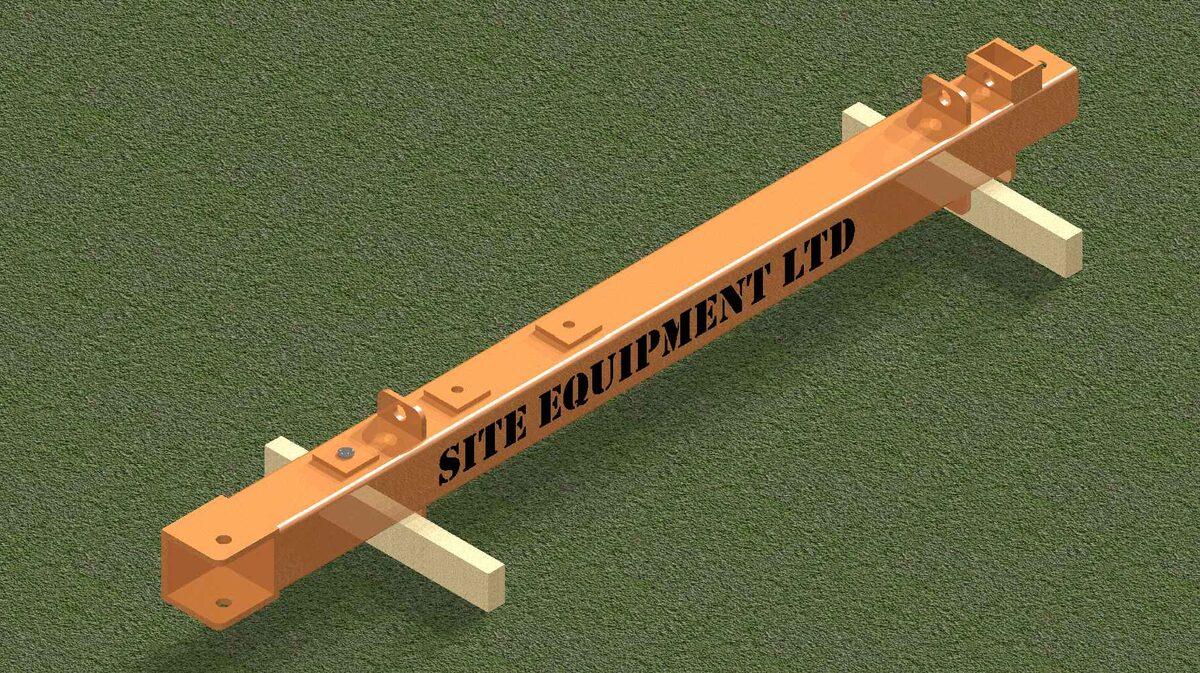
Lay first H-Series leg down on level ground on suitable timber bearers. Connect lifting hooks through the lifting points on the outer body.
For heavier frames, the legs can be assembled within the excavation at the level specified in the Temporary Works Design. Follow steps 1-3 within the excavation.
2. Assemble the frame
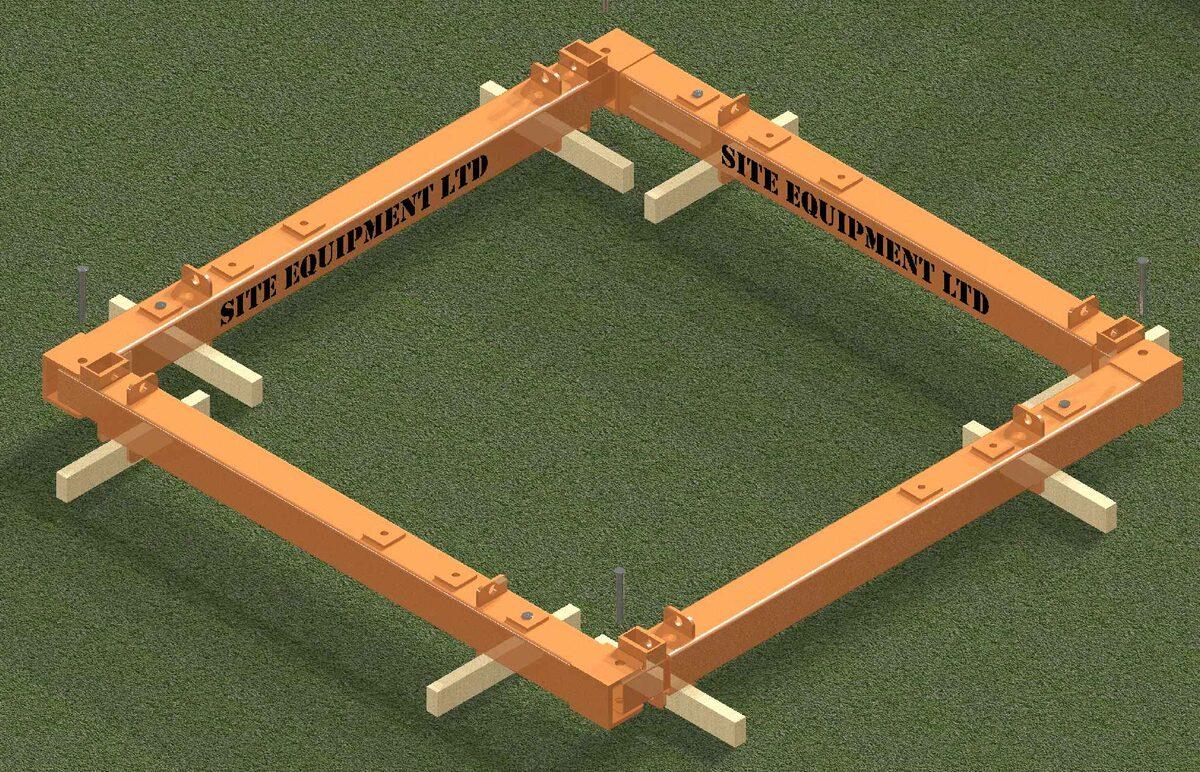
Lay remaining legs down as Stage 1 and insert a 40Ø Pin & R-Clip in each corner ().
Where required, set the coarse adjustment pin. To do this, remove the pin at the opposite end to the hydraulics, carefully pull out the inner section and reinsert the pin and clip.
3. Pump out the legs
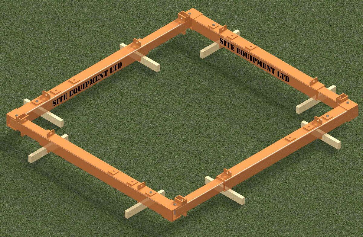
Using either the manual or hydraulic pump, connect both hoses to the pump, then to the H-Series legs. Ensure that the shoring fluid is no more than three quarters full to allow for expansion within the tank.
Pump out each leg to the required size (fine adjustment).
4. Pitch the corner sheets
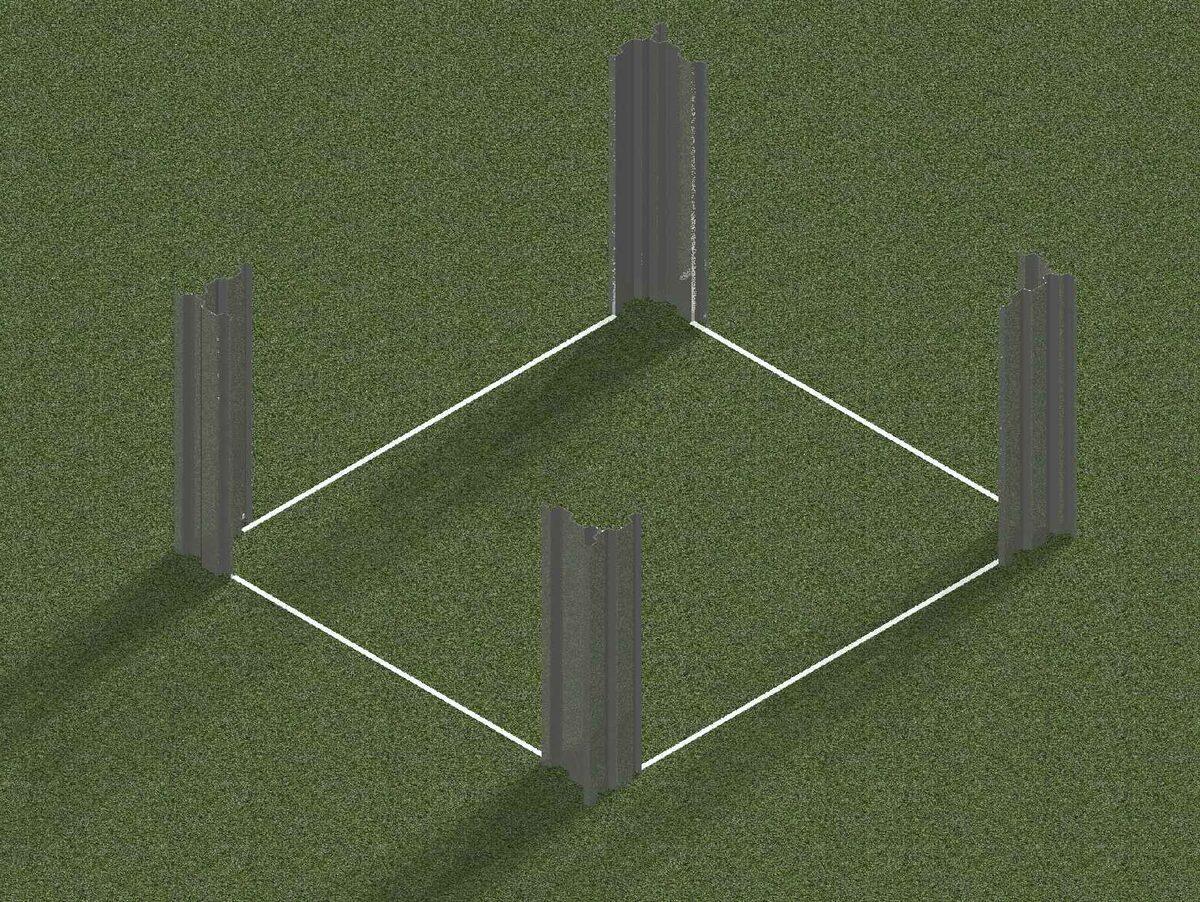
Mark out the line of the sheet piles.
Using the Driving Cap or Excavator Mounted Vibrator (EMV), partially drive the corner sheets first. Ensure that full manufacturer's instructions are adhered to where necessary. Further advice from a specialist contractor may be required.
5. Drive sheets and excavate
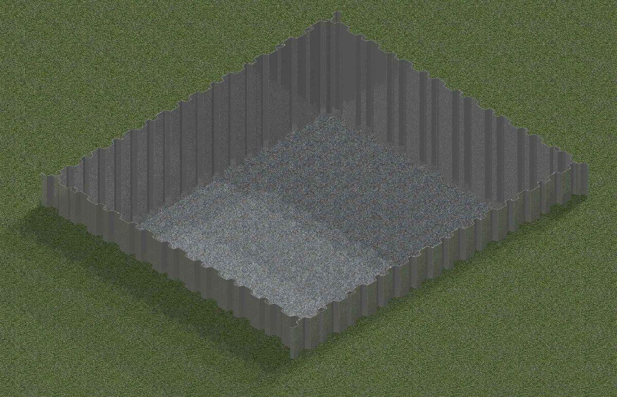
Complete driving of sheet piles to the required depth, usually the final toe level (or as per Temporary Works Design).
Excavate within the sheets to the underside of the first frame level - approx. 1.0m or as per TWD.
6. Install the first frame
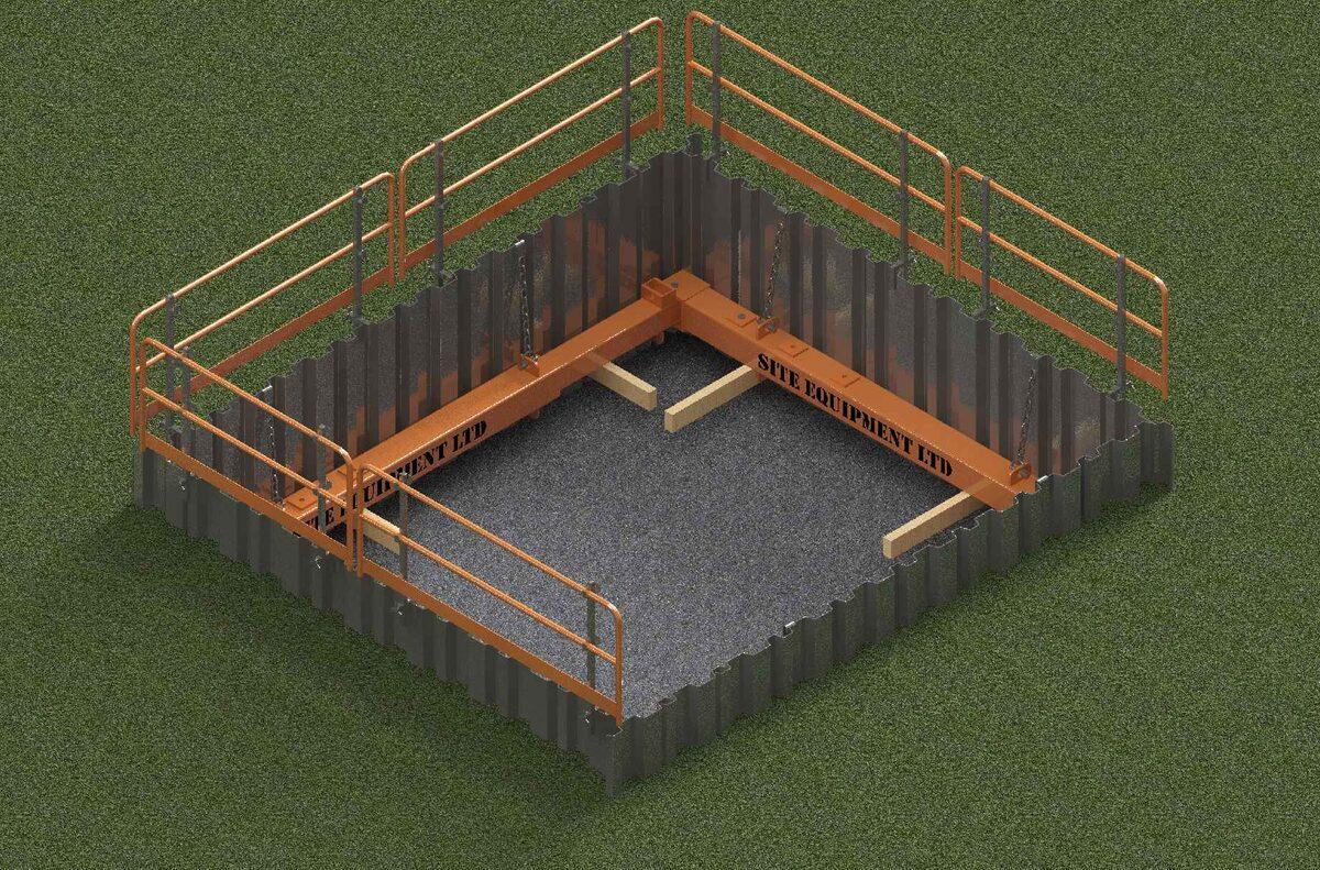
Lay timber bearers down within the excavation and using suitably load-rated lifting chains, lift the entire frame level into the excavation. Slightly pump in the legs to ensure ease of installation. Once installed to the correct level, pump out to the required size and install the restraint chains. Ensure lock-off valves are engaged.
Do not use the restraint chains for lifting.
7. Install further frames
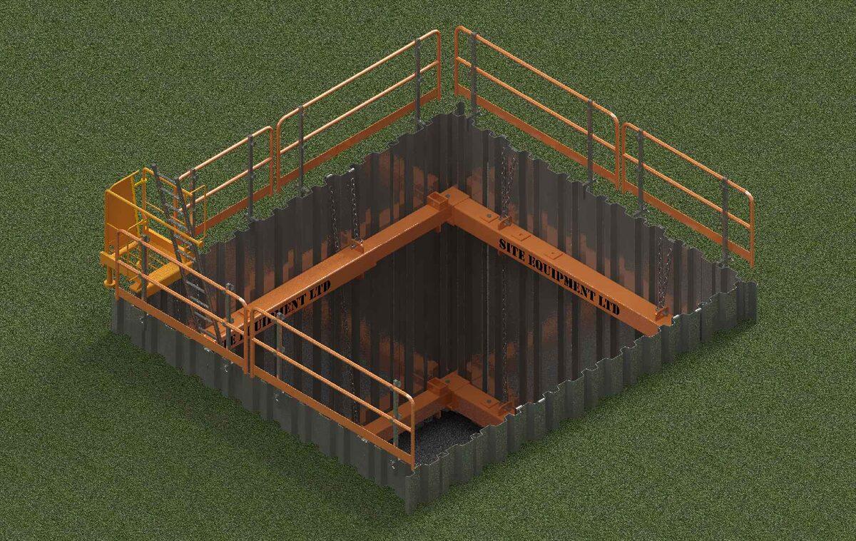
Excavate to the next frame level (as per TWD) and repeat Stage 6 with the next, and any following frame levels.
When lifting an assembled frame level down, ensure that it is retracted sufficiently to fit between the upper frames. If this is not possible, install leg by leg within the excavation.
Ensure suitable edge protection is installed, leaving a digging window if required.
8. Excavate to formation
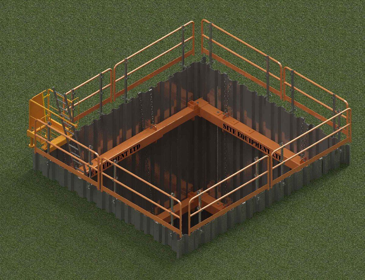
Once the lowest frame level has been installed, excavate to the final formation level and complete edge protection & access installation.
Removal
The removal of the equipment depends on the Temporary Works Design. There are two common scenarios which are described below for guidance only.
Two-Stage Construction - Casting of concrete base slab
- Prepare the formation adequately to enable a concrete slab to be poured.
- Cast a suitable concrete base slab ensuring contact with the sheet piles around the entire perimeter. Use plywood or other suitable separation membrane to enable extraction of the sheets.
- Once the slab can sustain the load identified in the TWD, remove the lowest frame level. Ensure that the weight of the equipment is adequately considered in the Lift Plan (by Contractor). The frame must be fully supported by suitable plant whilst the hydraulics are retracted and adequate access provided.
- Backfill the excavation in adequately compacted layers to the underside of the next frame level.
- Remove the next frame level and continue this process until ground level.
- Extract the trench sheets and reinstate accordingly.
Backfilling
- Once the works at formation level are installed, the excavation can then be backfilled in adequately compacted layers to the underside of the lowest frame level.
- Remove the lowest frame level either by retracting and lifting out the whole frame or leg by leg. Ensure the weights of the equipment are adequately considered in the Lift Plan (by Contractor).
- Continue the process of backfilling and removing frames until ground level.
- Extract the trench sheets and reinstate accordingly.
Please ensure all legs are fully retracted prior to collection.
Residual Risks
The following residual risks must be addressed in the Contractor's RAMS:
- Locate all potential services prior to excavation in accordance with NRSWA Regulations.
- The excavation may be classified as a confined space. The Contractor must assess this risk and provide suitable gas detection and rescue equipment where appropriate.
- The Contractor should always adequately consider the surrounding environment and account for adjacent structures, slopes, roads etc.
Do's and Don'ts
- Ensure an adequate Lift Plan is incorporated into the method statement (by Contractor) and pay close attention to the weights of individual legs (shown above) and whole frame levels.
- Carefully inspect all components and hydraulics prior to use. Contact SEL for advice where damaged components are found.
- Ensure all operatives are Trained & Competent and have been briefed on the requirements of the Temporary Works Design where necessary.
- Install suitable edge protection, access system and Davit system where required.
- Ensure appropriate vertical support is provided to the legs during installation and removal.
- Allow a minimum of 100mm extension on the rams to enable retraction when removing the equipment.
- Don't enter an excavation before adequate shoring is in place.
- Don't use hanging chains for lifting.
- Don't use faulty or damaged equipment.
Edge Protection & Access
Please contact Site Equipment for info on our full range of Access & Edge Protection accessories.