
 Contact us


Lite Trench Box Installation Guide
This is a step-by-step safe use guide covering how to assemble, position and then extract the Lite Trench Box, SEL's lightweight shoring system for shallow to medium utility excavations. Once assembled, the box should be lifted into a stable, pre-excavated trench up to 3.9m deep using an excavator or crane and a 4-leg chain sling.
Key Considerations
- Required Plant & Lifting Equipment
- Excavator or crane (<30T) · 4-leg chain sling
- Component Weights
- 743–1,637kg (base) · 406–875kg (top)
- Working Limits
- 3.9m max trench depth
- Site Conditions
- Stable ground · 4m from structures · 7m from roads/rail
Installation Sequence
Step 1: Lay Out the First Panel on Timber Bearers
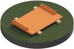
Using an excavator or crane and a 4-leg chain sling, lift the first Lite Trench Box panel and lay it flat on timber bearers on level ground with the vertical spindle channels facing upwards.
Attach the four chain hooks through the handling points at the upper and lower ends of both channels before lifting.
Step 2: Position and Pin the Adjustable Spindles
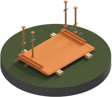
Spin out the four Adjustable Spindles to the required trench width and position one upper and one lower spindle vertically into each side channel, alternating the orientation of the threaded ends between corners so that one spindle in each channel has its screw thread at the bottom and the other has its screw thread at the top. Ensure that the two lower spindles are extended by 30–50mm more than the two top spindles.
Secure the base of each spindle into the channel using 2no Pins & R-Clips passed horizontally through the channel flanges (see a ).
Step 3: Lower and Pin the Opposite Panel
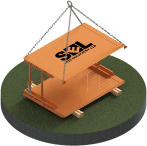
Attach the 4-leg chain sling hooks to the four handling points at the upper and lower ends of the opposite panel's channels. Using the excavator or crane, lift the opposite panel (with its channels facing downwards) and lower it onto the four upright spindles.
Secure the panel to the top of each spindle using 2no Pins & R-Clips passed through the channel flanges (see a ). Keep the chain sling under tension until all four spindles are fully pinned and clipped.
Safety check: Keep operatives' hands low down on the spindles when guiding the opposite panel onto them, and account for working-at-height risks when unhooking the lifting chains from the upper panel.
Step 4: Lift the Assembled Box Upright
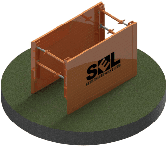
Attach the 4-leg chain sling hooks to the four upper handling points at the top of the panel channels and use the excavator or crane to lift the assembled box into its upright standing position.
For narrow trench boxes, temporarily place the upright box into a shallow, flat-bottomed starter trench on site to keep it stable before lifting it into the main excavation or fitting a top box.
Step 5: Attach the Top Box (Where Required)
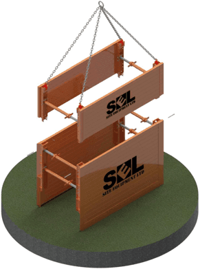
Where a Top Box is required for additional depth, assemble the Top Box flat on timber bearers and stand it upright following Steps 1–4 (a second spindle per channel may be used in the Top Box for ease of assembly). Using the excavator or crane and a 4-leg chain sling attached to the Top Box's upper handling points, lower the Top Box directly onto the upright Base Box.
Secure the Top Box to the Base Box at all four vertical channel joints using 1no Pin & R-Clip per corner (see a ).
Safety check: Keep operatives' hands clear of pinch points between the panels and vertical channels while lowering the Top Box onto the Base Box.
Step 6: Lower the Box into the Pre-Dug Trench
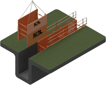
Using the excavator or crane and a 4-leg chain sling attached to the upper handling points, lift the assembled box and lower it into a pre-excavated trench dug in stable ground. A competent person must assess the ground conditions before installation to confirm the soil is temporarily stable and self-supporting (see Site-Specific Considerations).
Leave a minimum 50mm box upstand projecting above the surrounding ground level.
Step 7: Fit Edge Protection and Close Open Ends
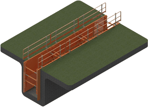
Fit suitable perimeter edge protection barriers and safe ladder access to the installed box where required. Ensure that any open ends of the excavation are either battered back to a safe angle determined by the Contractor or closed off using compatible end closure panels or supported trench sheets (see Installing with Additional Equipment).
Removal Instructions
Step 1: Backfill and Compact in 500mm Layers
Extract the Lite Trench Box sequentially once the permanent works are installed. Backfill inside the box in layers no deeper than 500mm and compact each layer to the Permanent Works design standard before lifting the box.
Step 2: Ease Each Corner and Lift up to 500mm
Using the excavator or crane with a single chain leg, pull each corner of the box slightly before attempting to lift the whole box using the 4-leg chain sling by a maximum of 500mm.
Step 3: Repeat Until Fully Extracted
Repeat this sequence—backfilling and compacting in maximum 500mm layers, easing each corner, and lifting the box up to 500mm at a time—until the box is completely removed from the trench.
Site-Specific Considerations
A Trained and Competent person must assess both the site and ground conditions.
The box is intended to be employed in ground which is stable and self supporting in the short term whilst installing the boxes to the final depth.
If any of the following ground conditions are anticipated / encountered, please contact SEL for advice as this box system may not be suitable.
- Unknown Ground
- Very Soft CLAY
- Very Loose SAND
- Silt
- Very Loose Gravel
- Peat
Careful consideration must be given to employing boxes in water bearing soils or in the vicinity of watercourses.
If anything beyond the following site conditions are anticipated / encountered please contact SEL for advice.
- Maximum excavation depth of 3.9m
- Maximum excavation duration <12 weeks
- Plant and machinery <30T operating near dig.
- No Structures located within 4m of dig.
- Adjacent slopes not in excess of +/- 1 in 10.
- No Services cross the path of the boxes.
- Deflection sensitive services not located within 4m of the dig.
- A live railway is not located within 7m of the edge of the excavation.
- Public Highway not located within 7m of the edge of the excavation.
- Suitable plant is available to lift and manoeuvre the selected box.
Residual Risks
The following residual risks must be addressed in the Contractors RAMS:
- When lowering the opposite panel onto the spindles, ensure operatives hands are low down on the spindle (Stage 3).
- Ensure operatives hands are kept clear of pinch points when lowering the top box onto the base box (Stage 5).
- When removing the chains from the opposite panel, consider potential working at height risks (Stage 3).
- Locate all potential services prior to excavation in accordance with NRSWA Regulations.
- The excavation may be classified as a confined space. The Contractor must assess this risk and provide suitable gas detection and rescue equipment where appropriate.
- If a spindle is struck accidentally by an excavator, inspect immediately. If damage is visible, remove the box from the trench and replace the spindle following the steps identified above.
Safe Usage Checklist
- Contact Site Equipment if unsure about any element of this document.
- Inspect all components to ensure that there are no signs of damage and that they are installed correctly.
- Ensure that the limitations of the box and this safe use guide is fully briefed to all operatives undertaking the work.
- Ensure suitable edge protection and access are provided as required.
- Ensure suitable lifting equipment is employed and suitable checks are carried out regularly.
- Ensure that the full height of adjacent soil is considered where a local ground reduction has been undertaken.
- Do not enter an excavation unless it has appropriate shoring in place.
- Do not have vertical earth faces at ends of boxes (see end closure options).
- Do not allow overdigging of the excavation.
- Do not allow storing of spoil or construction materials within 4m of the proposed excavation.
- Do not fly the boxes.
- Do not have out of balance digs.
Installing with Additional Equipment
Both ends of the boxes must be either connected to an adjacent box, suitably battered back, or closed off using suitable end closures (End Closure Panels or suitably supported sheets).
Do not use the spindles for support.
Please contact SEL for further information on our full range of end closure options and Access & Edge Protection accessories.